Sub-woofers - The crossover for the sub-woofers was the simplest. Generally I prefer low order, low Q crossovers. However, with sub-woofers I find that using a steep slope (3rd or 4th order) is important to avoid midrange muddiness that frequently shows up when sub-woofers are asked to pass anything but the lowest frequencies. I had been using Marchand XM1, 24db crossovers and a highly modified Hafler DH220 amplifier with good results. The only problem with this approach is that the XM1 crossover modules have a lowish input impedance that needed to be buffered. I also wanted to add a high quality attenuator so that the sub-woofer level could be easily fine tuned. high level diagram of the sub-woofer circuit that preceeds the Marchand crossover follows. |
Bass Horns - For the bass horns I needed both low and high pass filters. Simple first order filters are used. The crossover points are adjustable in precise repeatable steps using the switch blocks allowing for fine tuning. The high pass crossover combines with the acoustic roll-off of the bass horn for a combined 24db per octave slope, matching nicely with the 24db sub-woofer filter. The low pass crossover was more challenging. The bass horns have a fairly flat frequency reponse for a couple octaves above the crossover frequency. This would create significant acoustic overlap with the midrange horn. I could have used a Marchand XM1 filter here but was reluctant to insert a complex circuit with OP amps into this part of the signal path. As an alternative I designed an amplifier (LM3886 chip-amp) to drive the bass horns with an integral 12db roll-off that combines with the crossover circuit to form a low Q 18db filter. This was done without adding any additional components into the amplifiers signal path. |
Midrange Horns - In my experience the midrange is the most critical part of the audio spectrum and the place where quality matters most. So for the midrange horn the crossover is as simple and pure as possible. The crossover consists of a high quality Teflon capacitor loaded by a precision resistor block. With this arrangement the impedance of the amplifier will change the crossover frequency. To get the correct frequency I measured the input impedance of the amplifier and included the load in the crossover calculations. As with the bass horns the first order electrical crossover combines with the acoustic rolloff of the driver for a steep combined response. |
Tweeters - The tweeter crossover consists of a first order, adjustable high pass filter, a buffer and an attenuator to fine tune the tweeter levels. As with the bass horns the tweeter amplifer has a 3rd order low Q high pass crossover incorporated into it's design. |
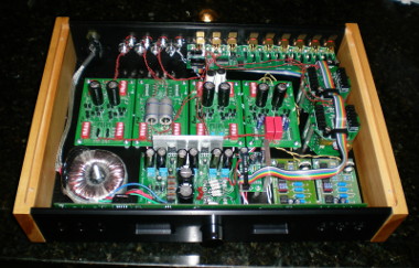
To create each of the individual crossover circuits I designed circuit boards that are sufficiently flexible to implement each of the circuits by populating different sections of the boards. Initially the crossover was built on a piece of plywood and then later was integrated into my passive preamp chassis. Adding the crossover into the passive preamp chassis continues the minimalist theme and eliminates an interconnect and 2 sets of RCA jacks. The schematic circuits are available here. |